A decemberi novella után most technikai poszt következik, vegyészkedni fogunk.
Írtam korábban egy posztot arról, hogy hogyan maratok NYÁK-ot. Most ismét a nyomtatott áramköri lap készítése lesz soron, ám ezúttal a maratási maszk elkészítésének egy egyszerű módszerét fogom megosztani a nagyérdemű olvasótáborral. A módszer túlmutat a nyákkészítésen, feliratozásra, ábrák fémfelületre vitelére, művészi kompozíciók fémbe maratására, és akár pecsétkészítésre is lehet használni.
Anyagszükséglete nem nagy, és nem drága. Szükségünk lesz egy számítógépre, egy lézernyomtatóra, műnyomó vagy fotópapírra, injekciós fecskendőre vagy mérőedényre, kis méretű üvegpalackra (kb. körömlakklemosó méret), ecsetre, konyhai papírtörlőre, és egy nehéz könyvre. És ami a legfontosabb, szükségünk lesz acetonra, és alkoholra. Ezeket én az Azúr vegyszerboltban vettem a József körúton, de aki nem pesti, annak azt tanácsolom, hogy vegyen akármelyik barkácsboltban denaturált szeszt, és akármelyik Rossmann-ban vagy hipermarketben acetonos körömlakklemosót. Én azért döntöttem az Azúr márkabolt mellett, mert tiszta vegyszereket akartam, de korábbi tapasztalatom alapján az acetonos körömlakklemosóval is működik a dolog. Olyat nem fogunk találni, amiben körömápoló olaj ne lenne sajnos, az a legjobb, ha ezen kívül csak aceton van benne. Sokszor raknak bele etil-alkoholt is, ami minket csak annyiban zavar, hogy elrontja a keverési arányokat, hiszen mi is alkohollal akarjuk keverni, és így nem fogjuk pontosan tudni, hogy mennyi acetonhoz mennyi denaturált szeszt töltsünk.
A teendőnk ezután a következő.
Készítsük el a nyáktervet valamely erre alkalmas szoftverrel. Nyomtassuk ki a tükörképét a műnyomó papírra. (műnyomó papírt fénymásoló üzletekben, papír-írószer boltokban vehetünk) Vágjuk körbe, tegyük félre.
Most jön a nyáklap előkészítése. Először is vágjuk ki a kívánt méretű nyáklapot, praktikusan egy lemezvágó olló segítségével. Régebben fűrészeltem, de egyrészt száll a por, másrészt sokáig tart. A lemezvágó ollóval egyszerűbb dolgozni. Ha a nyáklap nagyon régi, akkor törölgessük át egy sósavba mártott vattadarabbal, ami leoldja a barna oxidréteget, majd öblítsük le szappanos vagy mosószeres vízzel.. Ha a felület nem volt megbarnulva, akkor ezek a lépések kihagyhatóak. Ezután 100-as dörzspapírral alaposan csiszoljuk meg a nyáklapunkat. Ennek kettős célja van. Egyrészt eltávolítjuk vele a maradék felületi oxidréteget, másrészt a felület érdességét növeljük, amihez így jobban fog tapadni a toner festék. A csiszolást követően denaturált szeszes vattával még egyszer alaposan töröljük át a lapot, hogy a dörzsöléskor keletkezett réz és réz-oxid port eltávolítsuk. Innét kezdve csak gumikesztyűvel, esetleg nejlonzacskóba bújtatott kézzel fogjuk meg a nyákunkat.
Ezzel eljutottunk a lényegi részhez, a kinyomtatott ábra átviteléhez a nyáklapra. Ehhez régebben a vasalós módszert használtam, de nagyon nem voltam elégedett az eljárással, mert túl sok faktor volt, amit figyelembe kellett venni. Ezek a vasaló hőfoka, a vasalás időtartama, hogy mennyire kell rányomni a vasalót a papírra, milyen vastag a műnyomópapír... ez így már olyan sok tényező, hogy a végeredményhez legalább annyi szerencse kellett, mint tudás. Ezért döntöttem úgy, hogy vasalás helyett valami mással próbálkozom.
Az aceton remekül oldja a toner festéket, tessék nyugodtan kipróbálni. A baj vele az, hogy túlságosan is jól oldja, ezért ha tiszta acetont használnánk a nyákrajz átviteléhez, akkor a rajz körvonalai elmosódnának, a finom részletek összeolvadnának. Ezért kell az acetont alkohollal keverni. Az alkohol egyáltalán nem oldja a toner anyagát, ezért remek anyag arra, hogy az aceton oldékonyságát tompítsuk vele. A youtube-on találunk videókat erről a technikáról, ott 3:8 aceton/alkohol arányt javasolnak. Ezt én is kipróbáltam, teljesen működésképtelen. Csak egy csomó anyagot elpazaroltam vele. Nekem 2:1 aceton/alkohol arány működött, azonban ha valakinél ez nem válik be, akkor javaslom a 3:2 arányt. Ellentétben a youtube-os videókkal, az acetonból kell több!
Ha megvan a keverékünk, tároljuk üvegben. Enni nem kér, elvan mint a befőtt. Az aceton azonban megtámad sokféle műanyagot, ezért érdemes tényleg valódi üvegben tárolni. Egyszerre csak kevés kell belőle, szóval ha egy adagot bekeverünk, évekig elleszünk vele.
Akkor most következzék a festékátvitel leírása.
Helyezzük a kivágott műnyomópapíros nyáktervünket festékes oldallal lefelé a nyáklapunk megtisztított felületére. Ígazítsuk be a szélekhez. Ezután egy ecsettel kezdjük el a felfelé néző oldalát bekenni az aceton - alkohol keverékkel. Tocsognia kell, az a cél, hogy a papír átázzon. Amikor átázik, akkor a nyákrajz áttetszik a papíron. Ekkor kezdjük el az ujjbegyünkkel óvatosan nyomogatni. Fontos, hogy csak merőlegesen nyomogassuk, oldalirányban ne, mert ezzel elkenődhet a festék. Ha jól csináljuk, a papír odaragad a nyákhoz. Ekkor még egy kicsit kenjük át a papírt a keverékkel, hogy mindenhol egyenletesen áttetszővé váljon, majd az egészet nyomjuk le egy könyvvel. Kb. egy percig tartsuk rajta, majd hagyjuk, hogy megszáradjon a papír a nyákon. Mivel a keverék igen illékony, ez hamar megtörténik.
A megszáradt papír oda van ragadva a nyákhoz. Töltsünk a mosogatóba, vagy egy edénybe langyos vizet, és dobjuk bele a nyákot. Hagyjuk benn három-négy percig. Ennyi idő alatt a papír teljesen átázik. Ekkor gyengéd kézmozdulatokkal a papírt le tudjuk dörzsölni a nyákról, de a festék ott marad. Ha jól dolgoztunk, akkor a festék mindenütt egyformán letapadt, a kontúrjai élesek, és hűen követik a nyomtatott rajzot. A nyák készen áll a maratófürdőre.
Mint azt a bevezetőben említettem, a módszer alkalmas egyéb ábrák, pecsétek készítésére is. Ez utóbbi esetben a pecsét inverzét kell kinyomtatnunk, és átvinnünk a fenti módszerrel egy vastagabb alumínium vagy réz lemezre, majd ezt kell kimaratnunk. Ilyenkor nem jó a réz-klorid fürdős maratás, eleve maratófürdőt sem használhatunk. Réz esetében vas-klorid meleg sósavas oldata, vagy hidrogén-peroxid és sósav keveréke lesz a jó maratóanyag, de ami a lényeg, hogy a maratandó felületre rá kell csepegtetni, hogy lokálisan marjon. Elég macerás, mert sokszor ellenőrizni kell, hogy hol tart a folyamat, elég mély-e a vájat, de az eredmény kárpótol a fáradtságért. Ha kész vagyunk, a savat le kell mosni, és a maradványokat közömbösíteni kell szappanos, esetleg szódabikarbónás vagy trisós vízzel, majd egy használt fogkefe és némi fogkrém segítségével polírozzuk fel.
Ezután a kimaratott felületre kaucsukot vagy akrilt kell önteni, megvárni, míg megszárad, s a pecsét készen áll a használatra. Adná magát, de szilikon sajnos nem jó erre a célra, mert nem tapad hozzá a festék eléggé.
Én életem első pecsétjénél salétromsavat használtam maratószernek, rézhez. Ez sajnos ma már nem hozzáférhető (bár lehet otthon készíteni, ha valakinek van hozzá megfelelő felszerelése), így maradnak a korábban említett alternatívák. Illetve vannak továbbiak, csak senkit sem szeretnék arra biztatni, hogy akkumulátor savval dolgozzon. A maratóanyagot pipettával kell a maratandó felületre csepegtetni, időnként letörölni. A hidrogén-peroxid + sósav módszer lényegesen gyorsabb.
Ennyit mára a tudomány és a technika érdekességeiről.
A blogon korábban is volt szóelektronikáról, nemrég pedig a fa tartósítása kapcsán a kémia is képbe került. A mai bejegyzés a két tudományterület egyfajta metszete lesz, jelesül a nyomtatott áramköri lap maratásnak egy olyan módját szeretném ismertetni, amihez nem kell vegyszerboltba menni.
Mielőtt belevágnánk, zongorázzunk végig egy rövid átekintést arról, hogy milyen eljárásokkal szokás amatőr körülmények között a nyákmaratás elvégezni.
1. Vas-klorid: Ez a legnépszerűbb módszer. Elektronikai alkatrészboltokban, illetve a József körúti Azúr vegyszerboltban lehet beszerezni a vaskloridot oldat illetve kristályos formában. Az utóbbi esetben sárgásbarna anyagról van szó, amely egészen elképesztő ragaszkodással fog össze mindent a környezetében. Ha valahol foltot hagy, akkor attól nem igazán fogunk tudni megszabadulni. Alapesetben a használata úgy történik, hogy 1 liter meleg vízbe addig adagolunk állandó kevergetés mellett apróra morzsolt vaskloridot, amíg az oldat telítetté nem válik, magyarán több anyag nem oldható fel benne. Ebbe az oldatba kell belehelyezni a nyáklemezt, majd időnként ellenőrízni, hogy hol tart a rézfólia oldódása. Melegített oldat esetén 20-30 perc elég a teljes lemaródáshoz. A módszernek két hátránya van. Az egyik az, hogy tényleg mindent összefog, a másik az, hogy lassan kimerül. Szerencsére ez utóbbi ellen tudunk tenni, de hogy mit, azt majd később ismertetem. A reakcióegyenlet a következő:
Fe++++Cu = Fe+++Cu+
illetve van egy második lépés, bár ez a maratás szempontjából nem lényeges:
Cu++Fe+++=Cu+++Fe++
2. Sósav+hidrogén-peroxid. Ez a leggyorsabb módszer. Közönséges háztartási sósavba (minden boltban kapható szinte) belemerítjük a nyáklapot, majd pár kupaknyi 12%-os hidrogén-peroxidot adunk hozzá. Rögtön heves pezsgés indul meg, és mérgező klórgáz szabadul fel, ezért ezt a maratást csak szabad ég alatt érdemes csinálni. Előnye, hogy nagyon gyorsan lemarja a rezet a nyákról, hátránya hogy büdös és mérgező gáz fejlődik, a hidrogén-peroxidért fodrászboltot kell keresnünk, a marató anyag egyszer használatos, a hidrogén-peroxid magától bomlik, ezért nem tartható el sokáig. A reakcióegyenlet:
H2O2+2HCl=2H2O+Cl2
Ez a felszabaduló nascens klór reagál a rézzel:
Cu+Cl2=CuCl2
3. Nátrium-perszulfát, vagy ammónium-perszulfát. Ezeket az anyagokat elektonikai alkatrészboltokban vagy netről szerezhetjük be. Meleg, tömény oldatuk kb. a vas-klorid sebességével dolgozik, gázképződés nincs, az oldat átlátszó, idővel világoskék árnyalatú lesz, ezért a maratás folyamata a nyáklap kivétele nélkül ellenőrízhető. Az oldat sajnos kimerül idővel. A reakcióegyenlet:
Na2S2O8+H2O=Na2SO4+H2SO4+O
A felszabaduló nascens oxigén oxidálja a rezet, a keletkező rézoxid pedig oldódik a fenti egyenletben keletkező kénsavban. Az oldattal nagyon óvatosan kell bánni, mert fehér színű égési sérülést okoz a bőrön, a ruhaszövetet pedig szétroncsolja, ráadásul alattomosan, száradás után.
Én az első módszert használtam sokáig, és használnám ma is, ha nem lett volna több kellemetlen balesetem vele. Egy alkalommal rázógépre tettem a marató edényt hogy gyorsabban marjon, és kiborult a rossz beállítás miatt. A műhelyasztal fém részeit ahova odafolyt, ezután pillanatok alatt megette a rozsda. A kezemre ha ráfolyt, akkor napokig nem jött le, de nadrágom is bánta a cseppeket, amelyek a nyáklapról csepegtek le. A marási sebességgel sem voltam elégedett, ezért a módszert kénytelen voltam feljavítani. Ennek lényege az volt, hogy a vas-kloridot nem vízben, hanem tömény sósavban oldottam fel. Emellett elkezdtem levegőztetni az oldatot marás közben. Ennek vegyi funkciója és fizikai is volt, az utóbbi alatt azt értem, hogy keverte az oldatot, így jelentősen felgyorsította a maródást. A vegyi funkció még érdekesebb. A vas-kloridos maratáskor az történik, hogy a három vegyértékű vas ionok a réz felületén két vegyértékűvé redukálódnak, eközben az elemi réz pedig egy vegyértékű rézionná oxidálódik, majd ez további három vegyértékű vasionnal találkozva még tovább, két vegyértékű rézionná oxidálódik fel. Ez utóbbi lépés gyakran nem megy végbe teljesen. A levegőztetés során az oxigén visszaoxidálja a kétvegyértékű vasat három vegyértékűvé, és a maradék egyvegyértékű rezet is továbboxidálja kétvegyértékűve.
O2+4Fe+++2H2O= 4Fe++++4OH-
Eközben azonban ahogy az egyenletben is látható, hidroxid ionok képződnek, amelyek a réz és vasionokkal oldhatatlan csapadékot képeznek. Itt jön be a képbe a sósav, amely közömbösíti a hidroxidionokat, ezzel a csapadékképződést megelőztük.
H3O++OH-=2H2O
(A H3O+ a HCL hidrogénjéből és egy H2O molekulából a sósav vizes oldatában automatikusan összeálló oxóniumion - ami a savas kémhatást okozza)
Innét kezdve amíg a levegőztetést biztosítani tudjuk, és a rendkívül könnyen hozzáférhető sósavat pótoljuk, a rendszer önfenntartó. Nincs szükség több vaskloridra, akármennyi réz is oldódik fel, a maratószerünk továbbra is működőképes marad.
Felmerül a kérdés, hogy a keletkezett rézionok vajon nem zavarják-e a vasklorid működését?
A válasz az, hogy nem, sőt, segítik. Ugyanis az elemi rezet nemcsak a háromvegyértékű vas ionok, de a kétvegyértékű rézionok is tudják oxidálni. Igen, réz a rezet. Miközben a kétvegyértékű rézionnak a töltése eggyel csökken, és egy vegyértékű rézion lesz belőle, a nulla vegyértékű elemi réznek eggyel nő a vegyértéke, és szintén egyvegyértékű rézion lesz belőle.
Cu+++Cu=2Cu+
Amit a levegőztetéssel feloxidálunk a kiinduláskori kétvegyértékű rézionná.
4Cu++O2+2H2O=4Cu+++4OH-
Láthatóan itt elektronátmenet történik, a folyamat végén az összes réz feloldódik. A keletkezett OH- ionokat a feleslegben levő sósav közömbösíti. A maratószerünk tehát egyre jobb lesz.
Innét már csak egy rövid lépést kell tennünk a vasklorid mentes maratószer irányába. Mivel az eddigiek alapján a rézionok is képesek az elemi rezet oxidálni, adja magát a felismerés, hogy a vas-kloridra igazából nincs is szükség, és a nyáklapról feloldódó réz önmaga teszi egyre erősebbé és hatékonyabbá a maratószerünket, mindössze a levegőztetést kell biztosítani.
Ebben az esetben a folyamat elindítása az, ami némi gondot okozhat. Ugyanis ahhoz, hogy a nyáklapról a réz bekerüljön az oldatba, eleve szükséges valamennyi rézion. Ennek biztosításra három módszer áll rendelkezésünkre.
1. valamilyen rézvegyületet kell sósavban feloldanunk. A legkézenfekvőbb választás a réz-gálic, amit gazdaboltokban tudunk beszerezni, ebból készül a szőlő permetezésére szolgáló bordói por. De rézoxikloridot is oldhatunk sósavban, ez is egy gyakori és könnyen beszerezhető permetszer.
2. Elemi rézből csinálunk rézvegyületet. Ezt a következőképpen tudjuk megtenni. Rézdrótot kell szereznünk, lehetőleg vékonyat és több méternyit. Ezt gázlángon felhevítve a felülete megfeketedik, ami réz-oxid keletkezése miatt van.
2Cu +O2= 2CuO
Szerencsére a réz oxid remekül oldódik sósavban, ezért a megfeketedett drótot sósavba mártva a réz felülete letisztul, a sósav viszont megzöldül réz-klorid keletkezése miatt.
CuO+2HCl = CuCl2 + H2O
Az eljárást kellő számban megismételve össze tud jönni annyi kétvegyértékű réz ion amivel a buborékoltatós maratást már meg tudjuk kezdeni. Innét kezdve az oldatunk a nyákról beoldódó rézzel folyamatosan egyre jobb és jobb lesz. Célszerű az első maratások során a marató oldatot 40-50 fokra felmelegíteni, hogy a reakció sebességét megnöveljük.
3. A fentebb említett hidrogén-peroxidos módszerrel történő maratás utáni löttyöt is használhatjuk kiindulási anyagként. Itt is érvényes, hogy a buborékoltatás mellett melegíteni is kell az oldatot eleinte, mindaddig, amíg a nyáklemezekből elégséges mennyiségű rezünk be nem oldódott a maratószerbe.
Természetesen maradhatunk a vaskloriddal kevert verzió mellett továbbra is, ha nem zavarnak a foltok. Az egésznek az a lényege, hogy csak a legkönnyebben beszerezhető összetevőt, a sósavat kell pótolnunk, a maratószerünk nem fog kimerülni, és nem kell a környezetet szennyeznünk a kimerült oldat kidobásával.
As I mentioned earlier I designed some power amplifier for supporting my guitarist activity. What lead me to this hobby originated in the eighties. I was teenager then and had no money so I started to built simple guitar effects. Later as my knowledge developed, I begun making my own design what usually sounded better than the factory made circuits. Soon my interest turned to power amplifiers. I used a very poor sounding Regent 50G what was available then for the little money I had. Furthermore my father asked me to repair an old radio what used germanium power transistors which died. So I had two goals.
1. building a better guitar amplifier
2. repairing my father's old radio.
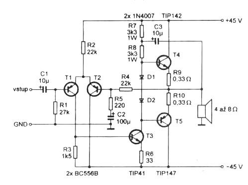
First I tried traditional schematics what helped me in the case of the old radio but didn't improved my guitar sound. As I examined deeply the problem I found that the traditional designs almost always use the power transistors as emitter followers, see below.
This is one of the most basic design of this area of electronics. In this configuration the power transistors amplify only current instead of voltage and current. Even it's true if complementer darlingtons are used instead of simple power transistors.This quite differs from the analogue case of tube amplifiers where the power tubes are allways used in grounded cathode configuration what results both voltage and current amplification.
Another problem with emitter follower configuration is that the power transistors need higher voltage drive than their emitters potential. It means that we cannot drive this kind of amplifiers's output to the whole range of power supply voltage without tricks. Necessarily its output must be less than supply voltage. If we applicate bootstrap then one power transistor's base ( T4) can be driven over the power supply voltage due to the fact that the bootstrap increase the driver voltage of this transistor over the positive supply voltage. But bootstrapping with capacitors results some problem about the phase transmission and I hear it as a strange squelch in the sound.
Nowadays everybody uses power mosfet transistors instead of bipolars. The widespread configuration of their using is quite similar to what we see above with some minor modification. They are more reliable than bipolar power transistors and sound better. In the other hand power mosfets need way higher drive voltage between their source and gate pole than bipolar transistors between their emitter and base. So the headrom is less if we use them in the traditional configuration.
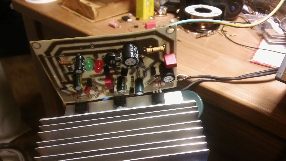
In my case I wanted to upgrade an old, transistor powered Marshall amplifier. It had symmetrical power supply voltage +20V and -20V. Well it is quite low so I need all volts for my poweramp's output to produce as much power as it can be possible. I decided to use power mosfet transistors instead of bipolars due to their characteristic is similar to vacuum tubes. So I had to find a special configuration where I can drive my amp's output from negative supply voltage to positive supply voltage, so in the whole range.
It was obvious for me from the beginning that the traditional configuration did not provide this. After analyzing the circuit I realized that the way of using the power transistors must be changed. I need configure them in grounded source mode instead of source follower. In this case these transistors would amplify voltage too and so they need way less drive voltage for getting the headroom reaches the whole range between negative and positive supply voltage. This drive voltage can be provided easily. Another point that they must be stabilized thermally. The typical IRF type power mosfet's drain current is increasing by the temperature if the gate voltage remains the same. Studying the graphs I found that I must decrease the gate voltage by 5,5 mV per Celsius if I want the drain current being the same. Silicone transistors base-emitter opening voltage changes by -2mV so I have two ways. I can use three of them before every power mosfet or I can use one for only the one of the mosfets and I set the DC voltage circuit gain to six times. The negative feedback then arranges to share this compensation between the two mosfets so at the end we get -6mV/Celsius on every mosfet. Of course I need more AC gain in the circuit but it can be arranged easily by capacitors in a proper positions.
Another point was that I needed the default output level to 0V what is exactly the center between the positive and negative supply voltage. For this the most reliable solution is a differential amplifier (actually a long-tailed pair) at the front of the circuit. There are another options but none of them is stable enough. There is a debate about using long-tailed pairs in poweramps as it can be the source of annoying transient intermodulation distortion called TIM. In the other hand in the case of guitar amplifier which has a way narrower frequency range than a HiFi circuit this point is not so relevant, and as I keep the open loop AC gain also low, it seems this problem is fixed.
Though my design starts with long-tailed pair just like the traditional one the similarity ends right here. I use totally different thermal stabilization and bias than the classical. Also I drive the mosfets different way which are in grounded source configuration contrary to the classical solution. This arrangement provides full power headroom, high thermal stability with simple construction.
Let's see the schematic then.
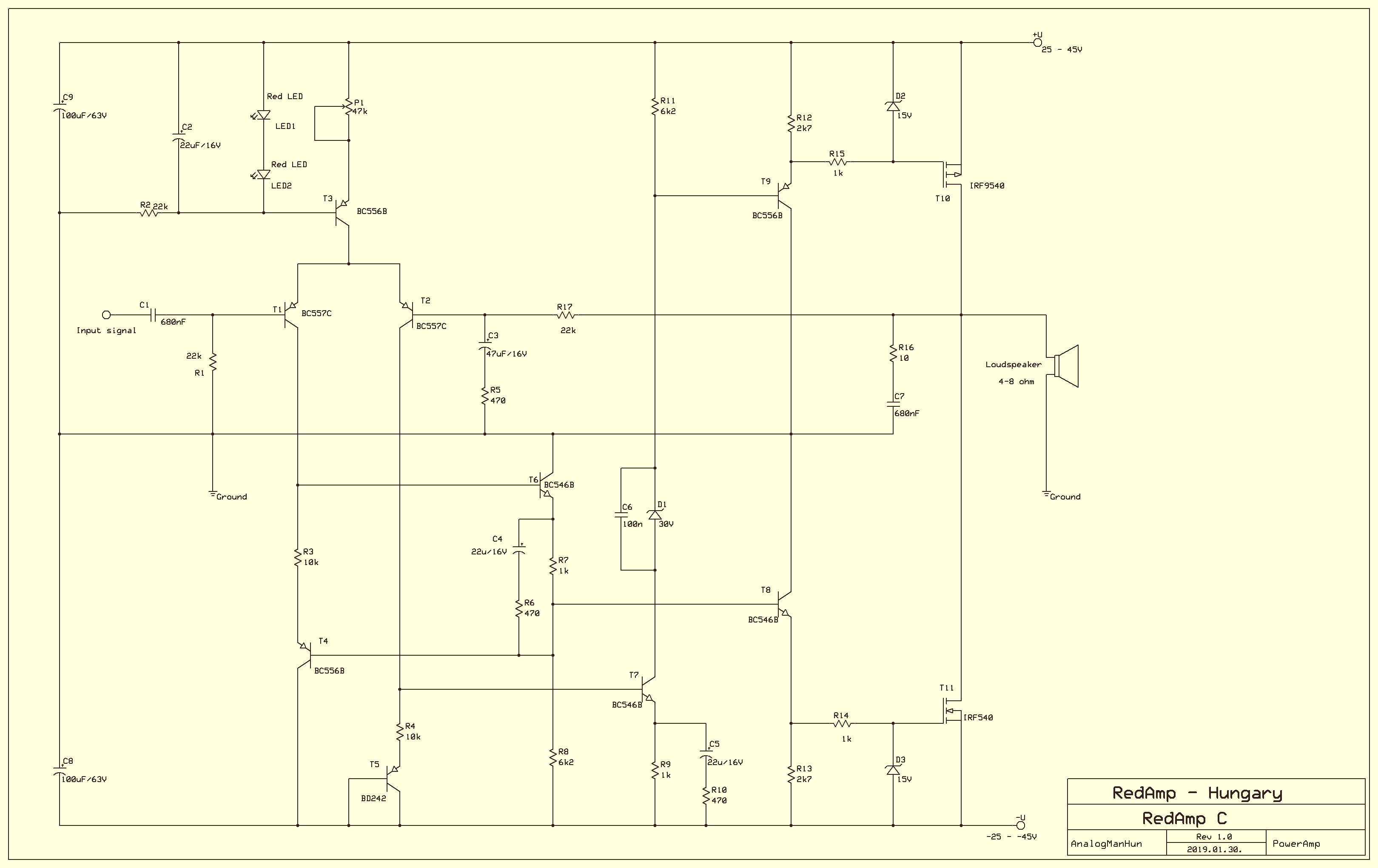
As the Figure 1 can be seen as the basic schematic of bipolar amps I think this Figure 2 has the right to be the basic schematic of mosfet poweramp technology due to its simplicity and because it uses all of the advantages of mosfet power transistors.
Let's see how it works. Practiced eye instantly recognises the usual long tailed couple (T1-T2) at the front of the schematic which works here as phase splitter. We use a current generator (T3) as emitter feeder for two goals. One point is it increases the amplifier's stability and symmetrical working. Second point that - instead of the practice of common bipolar amp circuits - we use it for biasing the output stage. My theory is that poweramp's DC gain shouldn't be enormous because we don't use it for amplifying DC but AC. Even more important principle that the power mosfets must be those parts where the biggest voltage (and current) amplifying should happen. For this goal I kept the DC gain of earlier stages as low as about 14 times. The long tailed pair amplifies only twofold and the second stage (T6,T7) does only less than sevenfold. Actually this is very good for thermal compensation. T5 is a transistor what must be applicated onto the heatsink the power mosfets are bolt on. So it is connected to them thermally. Every celsius grade increasing decreases the voltage on this part by 2 milliVolt. To stabilize a power mosfet thermally it needs 6 millivolt decrease on its gate by every celsius grade what means we have to amplify the decreasing on T5 voltage threefold. In the other hand it is enough only for the one of the two power mosfets (T10, T11) so actually we need sixfold DC amplifying after T5 then the negative feedback from the output takes care to share this compensation between the two.
As we see we drive the power mosfets by emitter followers (T8,T9). These provide low impedance which is good for fast charging and decharging the input capacitance of power mosfets (about 1-5 nF). In the other hand we use these capacitances to set the upper limit of frequency range this amplifier is working with. The human ear does not hear frequencies higher than 20kHz. It does not make sense to let this amplifier work with frequencies we even don't hear. Furthemore poweramps tend to produce unwanted feedback on higher frequencies what cases bad and unpredictable behaving of the circuit. So it is strongly suggested to limit the circuit to work only with that frequency range we hear. Or at least not so much wider range... That is why we drive the mosfets through R9 and R6 which consist low pass filters with the parasite gate capacitors of the mosfets.
We have not discussed only one interesting part of this circuit yet. This is a special arrangement of T4 and T6 transistors. It is quite rare to find this in circuits though it is not particularly complicated.
T6 seems to work in emitter follower mode. Actually it is wrong. It works in a grounded emitter mode but in this special case the ground is a floating one. The matter is that T1's collector sees T4's emitter as ground and the voltage what is a result of T1's current flows through R3 is relative to T4's emitter what is driven by that voltage what T6's current makes on R7 what depends on how much voltage of R3 drives T6 relatively to the voltage of R7.
Actually it is a kind of bootstrap but it uses transistor (T4) instead of capacitor. It results that T6 amplifies the voltage of R3 on R8 but contrary to the classical grounded emitter configuration it does it in same phase. The DC gain is the ratio of R8 and R7, the AC gain due to C3 capacitor and R6 is about 20. My theory is that the open loop gain of a poweramp - contrary to general beliefs - must be kept low because it prevents unwanted feedbacks and lets the mosfets express their good sound amplifying characteristics. It is also an effective method to avoid transient intermodulation (TIM).
We use this solution because we wanted symmetry between the two driver branch what lead to the two power mosfets. T7's role is unavoidable in this construction so I had to find a similar construction but with same phase amplifying in the other branch. That is why I used this special bootsrap solution.
So about the role of the zener diodes... This amplifier works with power supply +-25V to +-50V. There is only one transistor what is critical from this point of view. T7 works under almost the full voltage range from -U to +U. It means that the UCEOMAX of this transistor should be higher than this power range. In the other hand, BC546B's UCEOMAX is only 65V so we have to defend it from too much voltage. Actually it's collector voltage is not necessary be so high. What we need is its current what results voltage on R11. So we can separate the collector from this resistor by a zener diode what effectively decreases the voltage level at T7's collector. C6 shunts this zener's noise. Selecting the voltage of this zener diode there is one thumb of rule. The difference of the doubled supply voltage and the zener's voltage must be not higher than 60. For example if we use +-40 power voltage, the zener's voltage must be at least 20 Volt. If the power voltage is less than +-32V then rather leave out this diode and C6 capacitor by wiring T7's collector directly to R11.
D2 and D3 defend the gates of the power mosfets from too high drive voltage.
Of course the mosfets must be bolt on heatsink. The size of the heatsink depends on the power we want to get out of the amplifier. For 100 Watt you have to use +-40V power supply voltage. For 50 Watt the needed supply voltage is +-29V. If you want to use supply voltage higher than +-40 Volts I strongly suggest these:
1. use IRF640 and IRF9640.
2. double the mosfets. Use two IRF640 and IRF9640 instead of one. Use them in paralel position.
3. change the D1 zener to 50V zener.
Be sure that there is no short circuit between the mosfets and the heatsink. Use proper isolation parts.
P1 is responsible for setting the bias of the power mosfets. At the first run the variable pole must be set to the lower position what results that the trimmer's overall resistance is 47kiloohm. No we can roll carefully the pole slowly toward the upper position with very small steps. Meanwhile check the voltage between the source and the gate of T10. Around 3.3 Volt the mosfets start to warm up. Set a very little back the pole. Now we are at the safe bias level zone. Now we can attach the loudspeaker and give a signal to the input of the amplifier. If we still hear some harsh distortion then level up the bias a little bit. Though the amplifier is thermally compensated, it is not a magic tool. If we set the bias too high, the heat can kill the mosfets pretty soon so be careful.
The circuit is stable and relatively simple. It sounds differently to usual mosfet and bipolar poweramps, somehow more airy, but resembles to the famous VF2 circuit though more detailed and has better headroom.
Amplifier data:
Input resistance: 22 Kohm
Gain: 47
Open loop gain (without feedback): about 400. Depends on speaker's resistance.
Frequency range: 20Hz-30KHz
Output power: Depends on supply voltage. For 100W/8ohm, use +-40V. For 50W/8ohm use +-29V and leave out D1,C6, use simple wire instead of them. Do not use 4 ohm speaker if your power voltage is higher than +-33V.
This amplifier connects directly to the speaker so it is highly advised to use speaker defender circuit.
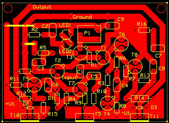
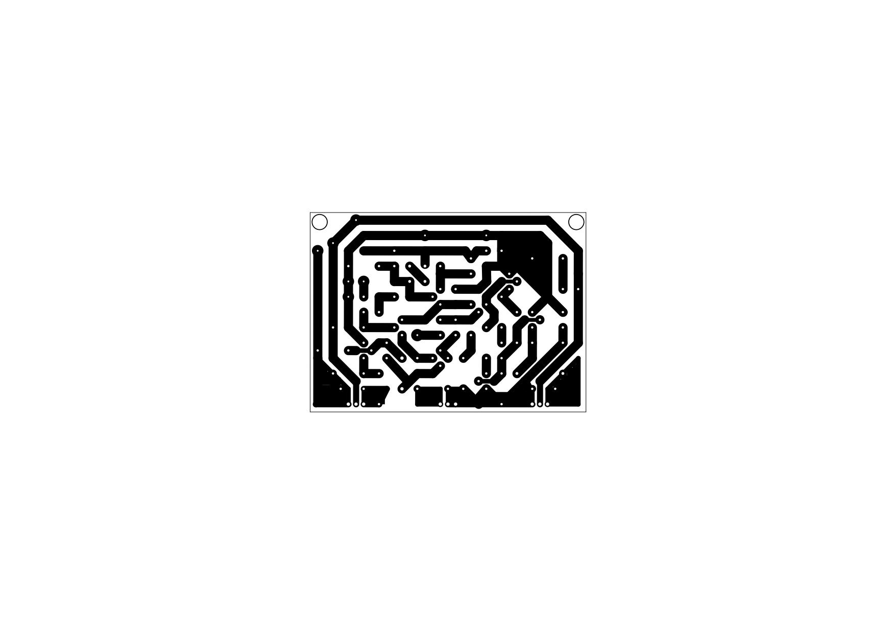
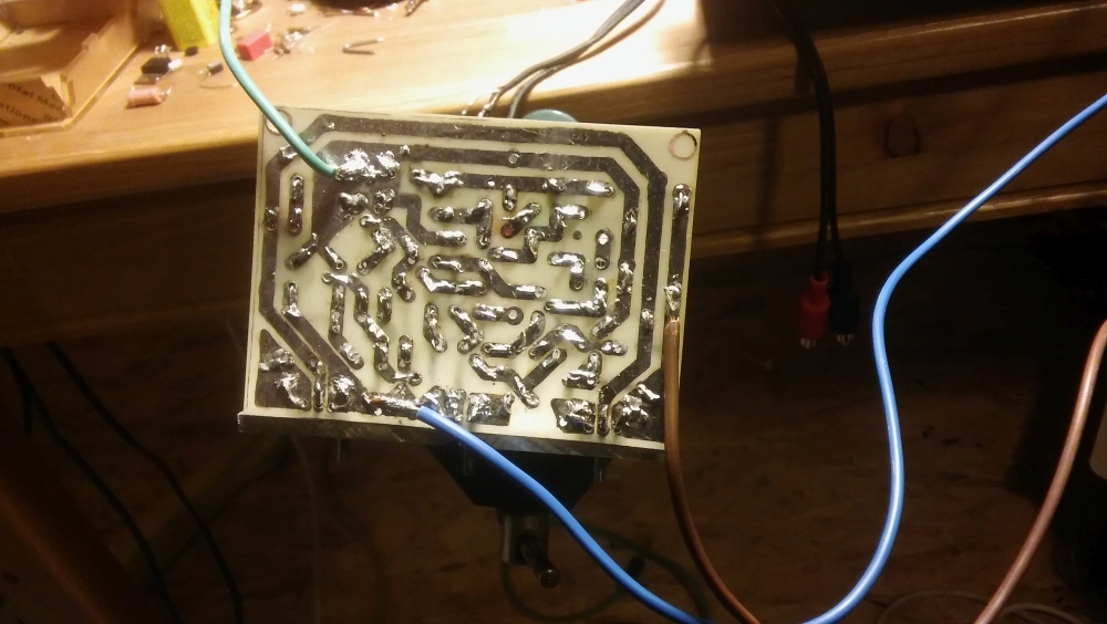
So download and print it. I use laser printer paper transfer method so if you use another method and have to mirror the pcb, do it yourself.
This is the component layout (the little pin on the transistor signs the emitter in this case):
And this is the pcb layout for printer transfer method (I hope it keeps its size. unfortunately this site doesn't let me upload pdf so I choosed jpg format. Download it then print. This should be one A4 page size in your printer):
One note to the PCB. I did not wired R5 directly to the ground, because I wanted to let the possibility of current feedback stay opened. So if you used this pcb plan just simply connect the small pane at R5 left side to the ground pane as I signed with a short yellow wire.
Let me know if anybody has questions. And sorry about my bad english.
Basically it is not a technical blog, furthermore its language is hungarian but sometimes I make exception. Especially in cases when the subject expects wider interest than it can get in Hungary.
I am an amateur guitarist. I started this hobby when I was teenager. The lack of money and the fact that I lived in countryside forced me learn how to build effect pedals for my guitar. Of course I started with copying simple and well known circuits but slowly my interest turned to create own ideas. I made more than hundred distortion circuit, each of them differs from the others. Later I had enough of distortions so I made octaver, phaser and wah pedals either.
As for the wah pedals, I built almost every kind of design. I mean Crybaby variants, T filter schemas, Wien bridge circuits. Actually there was only two what I really liked. These are the original Crybaby and a very tricky T filter circuit. The second one has a huge advantage upon the Crybaby circuit. It does not need coil for working.
Coils around the necessary value (660 mH) are not easy to get. You can buy them on internet, but these are not that usual cheap component we have used to.
Due to I prefer a little bit more the sound of Crybaby I decided to modernize this circuit. First I set criteria for my redesigning experiment.
1. The circuit must be based on the original Crybaby circuit.
2. The coil must be replaced by an RC based solution. (R: resistors, C: capacitors - these are easy to get). Obviously we have to use gyrator.
3. As gyrators are built of OpAmp integrated circuit and RC parts, it is quite plausible that we should use OpAmps instead of transistors in the other part of the redesigned Crybaby circuit too.
4. As my capabilities to create cog wheel mechanic are extremely limited, the circuit should be tuned by optoelectronic way. Plausible by LED and photo resistor. Shadowing is way easier to make than turning a potentiometer's axis by foot via mechanic cogwheel and cog lat.
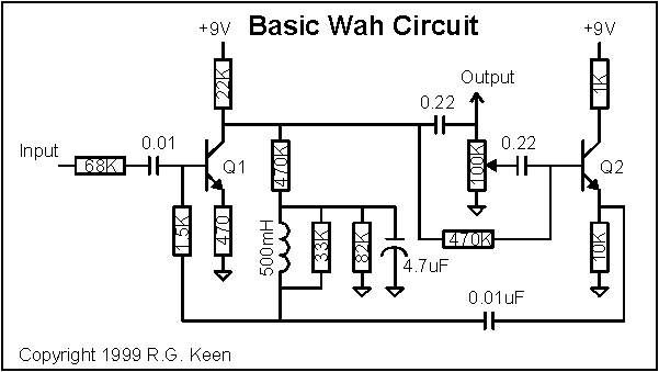
First let's see the original CryBaby circuit.
I decided replacing the transistors to opamps first. It is not as easy one can think. The circuit has a tricky bias feedback from the collector of Q1 through the coil and the 1.5K resistor to Q1 base. In the same time the coil is part of a paralel RLC filter which consists of the 1.5K resistor, the coil, the 33k resistor and the 0.01uF capacitor which is connected to the emitter of Q2. That is not easy to transform this biased circuit to one that uses opamps. Well, it is not entirely true. Q2 is replacable without any trick. Let's see.
The remained transistor is though. Let'see why.
It's biased by a negative feedback from its collector through the 470k resistor, the coil, and the 1.5k resistor. In these configuration - I mean with these emitter and collector resistors - its maximal gain is about 50x.
Other problem is that this biasing is good for a transistor but drives opamp out of its working range. Opamps usually should be biased to the center of their working voltage range. In this case we use 9V battery, so it means that practically we have to bias the opamps to 4.5V.
Furthermore replacing a transistor to an opamp which amplifies the signal more than hundred thousand times instead of a couple of hundreds - we can be sure it will effect drastically the frequency characteristic..
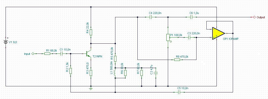
I modelled the whole process in Tina - which is a very good and free (with limitations) circuit designer and modelling program. I found that after replacing the first transistor with an opamp the circuit did not work as bandfilter (this is the key of wah effect) at all rather a distortion. So I decided to limit the gain of the opamp by negative feedback. I use the opamp in phase inverter mode according to the transistor's working mode - so I set its gain to 51x by using a 5.1Megaohm resistor and another 100Kohm. The last mentioned resistor leads the signal to the inverting input of opamp and the 5.1M also leads the feedback from the opamp's output to its inverting input.
Now my next task is taking care of biasing. As I previously mentioned, the opamps should be biased to 4.5V. To set this we need two resistor voltage divider between 0V and 9V. At its joining point we get 4.5V what I connected to the non inverting input of the opamp. The inverting input follows this value too through the negative feeadback I previously mentioned.
I checked the frequency characteristic and found that it works as bandfilter again and the transfer characteristic is just like the original CryBaby.
So ladies and gentleman, here is an opamp based crybaby clone! One point of my list is checked.
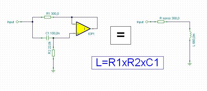
Now let'see the problem of coil. Generally coils made of copper wire and usually wrapped around a ferrit core. Thus their ohmic resistance is quite low. In our example it is about 10...30 ohm. Coils can be emulated by active electronic component coupled with resistors and capacitance. Actually capacitors behaves opposite than coils, their resistance decrease when frequency is increasing. With proper configuration this behaviour's opposite can be projected to a resistor which behaves after that very similar to coils. This configuration is called as gyrator. There are many type of gyrators, most of them are too complicated to applicate in our cry baby model.
Fortunately we can use some simplification. Though it is not so obvious but in our case the coil actually connects to the ground. True, there is a 4.7u capacitor between the coil and the ground but do not let us fooled. Its role is only to separate the transistor's DC bias feedback loop from ground. In AC point of view it behaves as shortcut. Especially on frequency range we are interested in. Remember, capacitor's resistance decrease with frequency increasing. A 4.7uF capacitor's resistance is negligible in this configuration above a 100 Hz compared to the other components resistance .
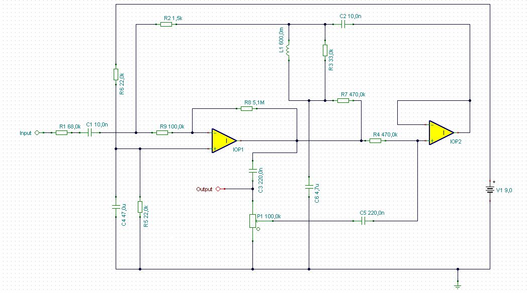
It means that we can use a very simple gyrator arrangement see below.
Ok, we are half ready. Now we have to figure out how to replace the coil with this. We have to bias our gyrator. Fortunately it is not as hard as it seems first. Note that the 4.7uF capacitor I mentioned earlier behaves like a shortcut to ground. It means that I can connect it to the gyrator's 22k resistor lower part as ground. In the other hand from DC point of view the capacitor upper part could be charged to 4.5V from the output of the first opamp via a 470k resistor. It is very similar to the original arrangement as the opamp's output acts the same role as the original transistor's collector, and the bias goes to the capacitor just like in the original and goes through the coil as here the gyrator. Then it finds it's way through the 1.5k resistor to the base of the transistor just like here to the input of the reduced amplifying opamp's input. See below how it is arranged.
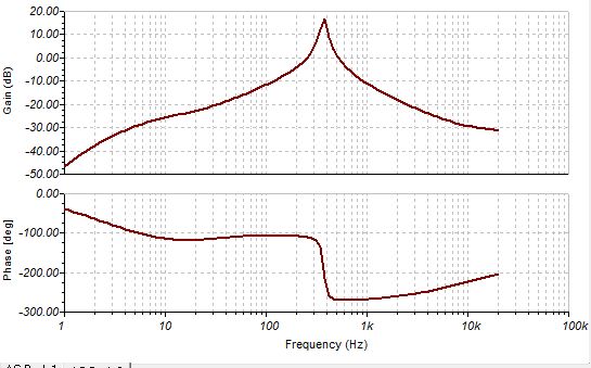
We are almost ready. Let's check its characteristic. The original Crybaby sweeps the 250Hz to 2000Hz range when you step on the pedal. This circuit is doing the same. Great. What it lacks is a magic factor, the Q. Q means quality here, actually Q has strong correlation with bandwith of the bandpass filter, and the gain of the resonant frequency. Graphically I can describe Q as sharpness of the frequency characteristic curve.
This is the frequency response of the original Crybaby at upper pedal setting (growl):
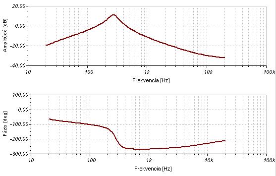
And see our circuit's with gyrator:
The difference is obvious. The gyrator has tenth higher serial resistance than the original Crybaby's coil so the sharpness of the frequency characteristic is way worse. Also the amplify factor is weaker at resonance frequency.
This is the point when experimenters usually give up the idea of replacing the coil with gyrator.
Actually either I did it. I started to develop this circuit twenty four years ago. True, there was no Tina or other modeling software then and I had only a Sinclair ZX Spectrum computer in those years.
I have had Tina for seventeen years but I focused my efforts to special MOSFET power amplifiers. Now I have found what I seek in that subject so I turned my vision back to guitar effects. So I picked up the gyrator wah thread again. My knowledge developed comparing to that I had at my first attempts. And I know tricks.
I do not deny, it is probably true that it is almost impossible to make a good crybaby with gyrator.
But again - I developed a trick. I improved the qyrator circuit a little bit to get what I want.
To understand this we have to discuss the working method of our gyrator. So let's check again the scheme:
What we see is that there is a capacitor which connects to the non inverting input of the opamp. Also we have a resistor here what connects to the ground. As the frequency is increasing the resistance of the capacitor decreases so the signal at the non inverting input gets closer to the signal at the input of the whole circuit. Can you follow me?
So at higher frequencies the non inverting gate of the opamp follows better the original signal thus the output of the opamp does the same. It means that in high frequencies the signal is almost the same at the two end of R1. It means that the higher the frequency the lower current flows through R1. Great. It behaves just like coils.
So somehow I have to improve this attribute of our gyrator. Fortunately I can do that. The goal is that the circuit must keep its frequency response and should increase the current flow as expected. In this case from outer view the circuit would behave like it has less serial resistance because more current would flow by the same input signal.
The basic gyrator's opamp's gain is unity. If we turn it to higher than one then extra current has to flow through R1 due to the higher potential difference.
We have to be very careful. If the gain of the opamp became too much then the resistance of R1 become virtually negative and the circuit loss the ability to emulate coils.
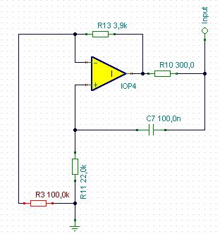
I found that a very little rising in the gain effectively decreases the apparent serial resistance of our gyrator. Actually the gain factor here is 1.039. That does the trick.
That final values for the necessary 660 mH coil replacement and the configuration can be seen below:
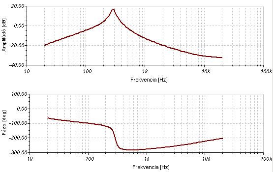
Now let'see the frequency response.
Well, that is quite good. The shape could be even better with precise tuning capacitor and resistor values but I think this result is still acceptable with these values. It really sounds like the original.
Now I complete three point of four. One remained, the optical tuning. Though mechanically it is way more simple than the cog wheeled potentiometer and practically noise free, in the other hand there are some disadvantage either.
All optical tuning circuit use photo resistors and LEDs. The problem is, that photo resistors are not perfect for controlling. They have relatively high resistance even at full illumination. Also their resistance is not enough high at full dark. Even they show some delay in following changes of illuminaton. Fortunately this delay is quite small and indifferent in our practice of tuning wah pedals.
So the main problem is the control range of resistance change is too narrow. Potentiometers are way better in this subject. What to do now?
The solution is relatively simple, but we must understand first, how Crybaby tuning works.
I previously mentioned that the Crybaby circuit is actually a band pass filter. There are many bandpass filter topology, both active and passive. Crybaby is an active LC filter where the capacitor is tuned electrically. Filtering happens before the first electric component and passive components provide that. The role of the active component ( transistors) is to amplify and create reversed phase signal at the other end of the filtering capacitor (10n) to emulate higher capacitance - depending on the potmeter setting. The higher reversed phase signal gets to the second transistor the higher capacitance is showed by the capacitor from the emitter of this transistor.
So our goal is to control the signal level what gets from the collector of the first transistor to the base of the second transistor. Actually in the new circuit it means controlling the level of signal from the first opamp's output getting to the second one's input. Let me note that we use TL071 opamps (or a TL074 quad opamp IC) which have jFet inputs. What is important, we must control this signal totally. For higher frequencies we have to block entirely the signal getting to the second opamp. For low frequencies we have to pass the full signal to the second opamp. The limitations of photo resistors don't let it to be suitable for this requirements so we have find another solution. I decided to use a voltage divider, where the lower resistor is a jFet. Its channel resistance can vary in extremely wide range from 500 ohm to Gigaohms depending on its gate-source bias voltage. It has minimal resistance between the drain and the source when gate-source voltage is 0 or greater and maximal (practically infinite) when the gate source voltage around or less -2V.
So we can control this element by negative voltage. In the other hand we have positive voltage range from the ground to 9V so we create a virtual ground at 4.5V using an opamp which non inverting input is set to 4.5 V so the output is on the same voltage. In advance this virtual ground gives the correct bias for the whole Crybaby circuit so it has double usage.
Back to the signal control. We put the controller jFet's source on the virtual ground so we can drive its gate by lower voltage in the lower 4.5V range of the original 9V supply voltage. Great. For the controlling voltage now we can use our photo resistor as a lower component of a voltage divider. Its lowest resistance in full illuminating is about 8 kohm. In total absence of light its resistance is about 500kohm. Thus we have to use a 10 kohm resistor as the voltage controller upper member. At full dark the photo resistor's resistance becomes 500 kohm thus the control voltage is almost 4.5V which is equal to the virtual ground's value which is the jFet source value also. In this case the FET is open and it shunts the signal to the virtual ground instead of letting it to the second opamp. In total illuminating the photo resistor's resistance is about 8 kohm which set the controller voltage to 2.25 V lower than the virtual ground voltage. It closes the jFet so it passes the signal to get to the second opamp. In intermediate setting part of the signal is shunted, other part is passed. Just like the potentiometer do in the original circuit.
After solving the problem of optical control I made three minor change. First I changed the 100k resistor which is paralel with the gyrator to 1M. It sharpens the bandpass curve a little bit.
Second I changed the first opamp configuration from inverting to non-inverting mode by choose its non-inverting input instead of the inverting one. Meanwhile I did the opposite with the second opamp because this circuit works only if the signal's phase is inverted before it is feedbacked to the 10n capacitor.
Third I put a source follover jFet stage before the whole circuit to avoid tone sucking what is an unpleasant disadvantage of basic crybaby circuits. I choose jFet here instead of
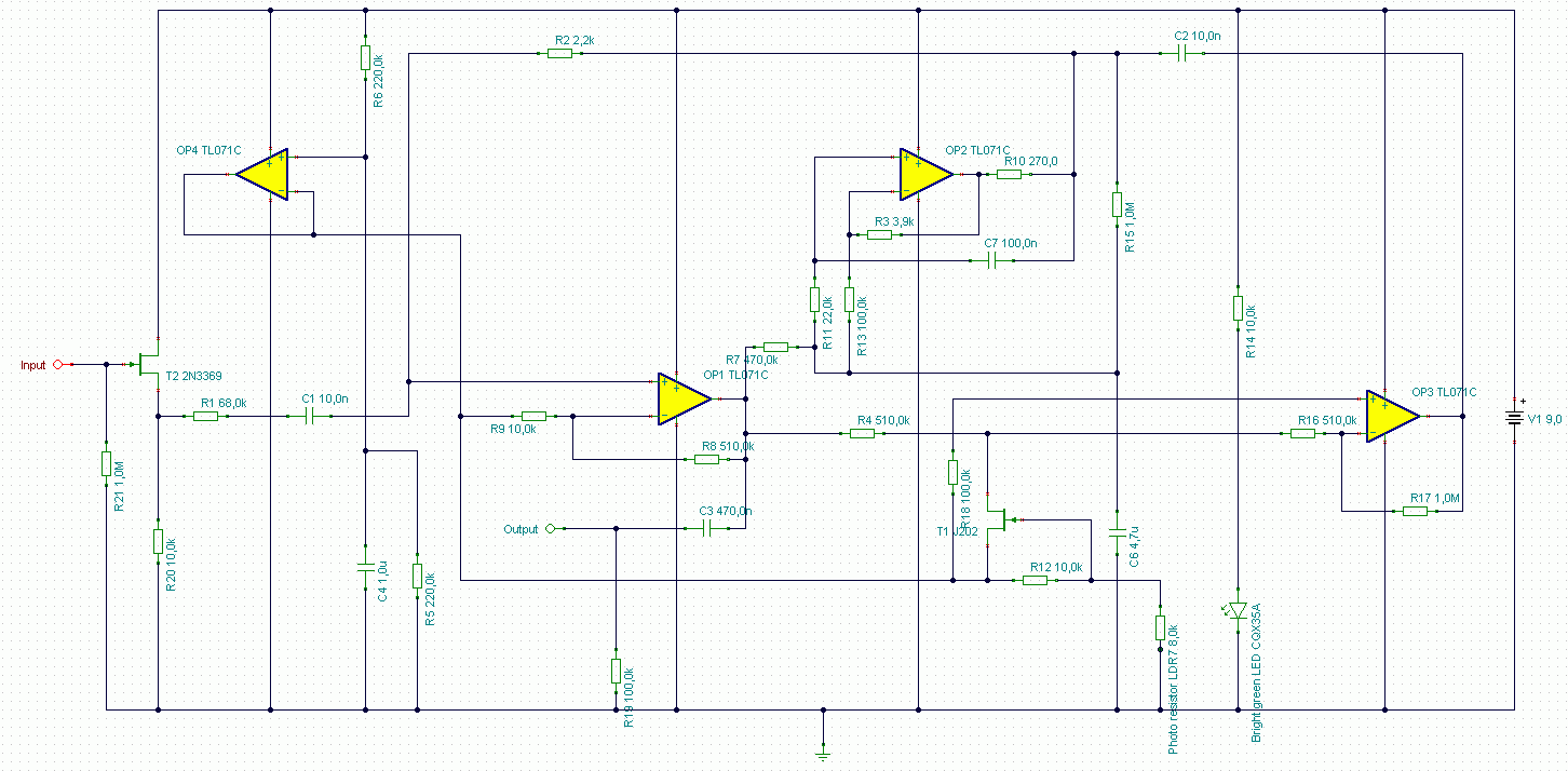
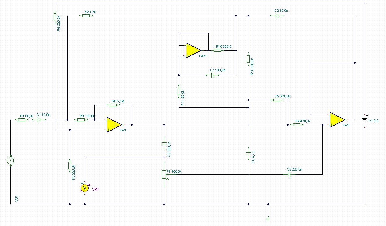
Now let's see the completed scheme:
This is a fully functioning circuit what sounds very close to the original Crybaby wah. Powered by 9V battery.
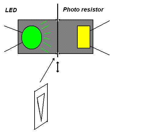
At last some words about optical tuning. As I mentioned above, it works by shadowing. Practically it means that we put the photo resistor into a black tube. At the other end of the tube there is a bright green LED. Yes, green due to the photo resistor's peak sensivity is at 540nm wavelength of light. That means we have to use green LED to provide such a light. During tuning we move a thin metal sheet between the LED and the photo resistor. It contains a triangle shaped hole. Depending on what part of the hole is between the two element different amount of light is blocked which drives the photo resistor's resistance. See below.
This is a fully functioning circuit what sounds very close to the original Crybaby wah. Powered by 9V battery. Good luck for constructing and sorry about my bad english.
 We are almost ready. Let's check its characteristic. The original Crybaby sweeps the 250Hz to 2000Hz range when you step on the pedal. This circuit is doing the same. Great. What it lacks is a magic factor, the Q. Q means quality here, actually Q has strong correlation with bandwith of the bandpass filter, and the gain of the resonant frequency. Graphically I can describe Q as sharpness of the frequency characteristic curve.